How an Oil Pump Jack Works: Rod Lift, Controls and Where AI Fits
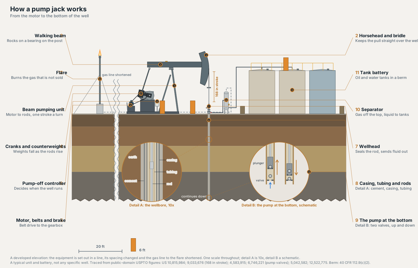
An oil pump jack turns a motor's rotation into a straight pull, up and down over the well. On the unit we modelled that pull is 14 feet long and repeats seven and a half times a minute. We built it the way we built our jack-up rig and our AI data hall: a typical unit and the small tank battery it produces into, traced from public patent drawings, then cut open so you can follow the chain from the motor to the pump at the bottom of the well. The tour runs 47 seconds with no sound, and every label is on screen.
Take it apart yourself.
The model runs in your browser, and the unit keeps pumping while you look. Drag to turn it, take it apart with the slider, and press Cut it open to take the ground away and watch the rods moving inside the well. It works on a phone.
It sits beside our three offshore structures and the data hall. See all the exhibits.
What you are looking at
Follow the motion from the motor to the bottom of the well, then follow the fluid back out to the tanks.
- Motor, belts and brake. An electric motor drives the gearbox through belts. The brake lever at the back of the base stops the cranks.
- Gearbox, cranks and counterweights. The gearbox slows the motor down to the stroke rate and turns two cranks. Heavy counterweights on the cranks fall while the rods rise, so the motor is not lifting the whole rod string by itself.
- Pitmans and walking beam. A pitman connects each crank to the back of the beam. The beam rocks on a bearing at the top of an A frame called the Samson post.
- Horsehead and bridle. The curved front of the beam. A wire rope bridle hangs from it and holds the polished rod, the top of the rod string.
- Wellhead. The polished rod slides through a stuffing box that seals around it. A tee below sends the fluid out along the flowline.
- Casing, tubing and rods. Steel casing cemented into the hole, tubing hung inside it, and the rods moving inside the tubing.
- The pump at the bottom. A barrel, a plunger and two ball valves, too deep and too small to draw at true scale.
- Pump-off controller. A cabinet on a post beside the unit that decides when it runs.
- Separator. Oil, water and gas arrive together. Gas leaves from the top, liquid from the bottom.
- Tank battery. Two oil tanks and a water tank inside an earth berm, with a catwalk across the tops and a load line for trucks outside the berm.
- Flare. Gas that is not sold is burned here, set well away from the tanks.
How one stroke lifts oil
One turn of the cranks is one stroke, up and then down. Because the face of the horsehead is an arc centred on the beam's bearing, the bridle pulls straight up and down over the well however far the beam tips.
At the bottom of the well, the pump does the actual lifting with two valves (US 6,746,221). On the upstroke, the traveling valve on the plunger closes and the plunger lifts the fluid above it, while the standing valve at the bottom of the barrel opens and lets the well's fluid in below. On the downstroke they swap: the standing valve closes, the traveling valve opens, and the plunger moves down through the fluid that just came in. Fluid only ever moves one way, up the tubing toward the surface.
The unit we scaled from is a 640-365-168 (US 9,033,676). The last number is the longest stroke in inches, 168, which is 14 feet. In that patent's test well, 9,057 feet deep, the rods ran in five sections of different diameters to a 1.75 inch pump, and the unit was run at 6.3 and at 7.6 strokes a minute. Ours runs at 7.5. By our arithmetic that is 450 strokes an hour and 10,800 a day.
Why most of these run alone
The US Energy Information Administration counted 918,481 producing oil and natural gas wells in 2024, and 78% of them produced 15 barrels of oil equivalent a day or less. That count covers oil and gas wells together, and it is not a count of pump jacks: the report does not say how each well is lifted. EIA has also said it is discontinuing the report. What the count shows is the shape of the fleet. Most US wells are small producers spread across a lot of ground.
A study of rod pumped wells in Brazil put the consequence in one line: "there are many wells for a few operators" (Nascimento et al., 2021). So the unit runs on its own, a lease operator drives a route of wells, and a controller beside each one decides when it pumps.
The controller decides when it pumps
A well gives up fluid at its own rate. Pump faster than it refills and the barrel at the bottom only partly fills, so on the downstroke the plunger hits fluid instead of moving down through it. That shows up in the load measured at the surface. A pump-off controller is built to catch it: a load sensor and a position switch on the beam tell it the load on the rods at each point of the stroke, and when that load says the well is pumped off, it stops the motor, lets the well refill, and starts again (US 4,583,915).
Plot that load against the beam's position over one stroke and you get a closed loop called a dynamometer card. Its shape is the main way anyone judges how a pump they cannot see is doing.
Then there are the settings. Someone sets the load limit the controller acts on and how long the well rests. Those settings decide how much the well makes and how hard the equipment is worked. Who can change them, from where, and who hears about it when they change is a decision, not a default.
The tanks are a safety question
Measuring a tank by hand means climbing to the catwalk and opening the thief hatch on top. OSHA and NIOSH identified nine workers who died from 2010 through 2014 while manually gauging or sampling crude oil production tanks: three in North Dakota, three in Colorado, and one each in Texas, Oklahoma and Montana. Four were gauging and five were sampling. In every case, the alert says, the worker was alone or not being observed by a co-worker. The first engineering control it lists is remote or automatic gauging and sampling, so a tank can be measured without anyone opening it. A CDC report on nine deaths of this kind, January 2010 to March 2015, found all of the victims were working alone (MMWR, 2016).
The berm is the other rule drawn on this pad. Federal spill rules for production sites call for secondary containment for the entire capacity of the largest single tank, plus freeboard for rain (40 CFR 112.9(c)(2)). One patent sets a tank at least 50 meters from the flare stack, for safety (US 5,042,582).
Twelve systems, and what controls them
Each system in the interactive pump jack has its own link, which opens the model on that part with a short explanation and a line on what is measured or decided there. That second layer is operational technology (OT): the controllers, sensors and gauges that run the site, as opposed to the office systems that report on it.
| System | What runs or decides it |
|---|---|
| Beam pumping unit | Mostly runs with nobody there. Each stroke is measured at the beam, and a controller at the well decides when it runs and when it rests. |
| Horsehead and bridle | A load cell under the carrier bar, or a sensor on the beam, measures the load on the rods. That reading is what the controller works from. |
| Walking beam and Samson post | The load sensor and position switch on top of the beam are the pump-off controller's inputs. |
| Gearbox, cranks and counterweights | Imbalance shows in the motor current and in gearbox torque worked out from the load data. A technician decides when the weights move. |
| Motor, belts and brake | The brake is set and the power locked out before anyone works on the unit. Some wells vary motor speed within each stroke under software control. |
| Pump-off controller | Compares load with beam position every stroke and stops the motor when the well is pumped off. Someone sets the limit and the rest time. |
| Wellhead | Pressure gauges and the stuffing box, checked by the lease operator on each visit. |
| Casing, tubing and rods | Watched through the load measured at the surface. A hole worn in the tubing means a crew and a rig to pull everything out. |
| The pump at the bottom | Nothing measures it directly. A barrel that does not fill shows up in the load at the surface. |
| Separator | A level controller holds the liquid between two limits and opens a valve to send it to the tanks. |
| Tank battery | Level gauges read remotely, or a person on the catwalk with the thief hatch open. |
| Flare | Flow can be metered, and a flame detector shows whether it is lit. Flaring instead of shutting the well in is a person's call. |
Eight places AI fits, and where it has to stop
Every stroke at every well produces a load reading, and most of the pad can be measured. That makes each part a candidate for AI, and it makes the governance question concrete. The table is our read of where analytics adds the most and who should still own each decision. Only the second row has a published study behind it, and that is one study; the rest is a map of opportunity, not a list of what any operator runs today.
| System | Already measures | What AI could add | Who should decide |
|---|---|---|---|
| Pump-off controller | Load and beam position every stroke; run and rest times | Suggest each well's pump-off limit and rest time from its own history, instead of one setting copied across a field | Production engineer. The controller's own shutdown stays in the controller |
| The pump at the bottom | The load against position card drawn at the surface | Sort the cards by what they show, so a person reads the odd ones first. One study, 38 wells near Mossoró in Brazil, reported a best accuracy of 99.84% against cards classified by experts | Production engineer. A model from one set of wells is evidence about those wells |
| Casing, tubing and rods | Surface load, and each well's failure and workover history | Rank wells by the risk of a rod or tubing failure, so the workover rig goes where it is needed next | The superintendent who schedules the rig |
| Gearbox, cranks and counterweights | Motor current; gearbox torque worked out from the load data | Flag a unit drifting out of balance between visits | Technician, who decides when the weights move |
| Motor and drive | Motor current and speed | Tune the speed within each stroke, inside limits the drive and the rods allow | Production engineer sets the limits. The brake and lockout stay manual |
| Tank battery | Tank levels, where remote gauges are fitted | Forecast when each tank fills and plan trucks around it, so fewer trips need someone on the catwalk | Lease operator and supervisor. When a person still climbs is a safety rule, not a model output |
| Separator | Liquid level and how often the dump valve opens | Spot a level controller or dump valve that is sticking | Lease operator. The vessel's own protection stays where it is |
| Flare | Flow to the flare where it is metered; flame detection | Flag a flare that has gone out, or a flow that does not match what the separator sent | Lease operator and supervisor. Flaring instead of shutting the well in is a person's call |
The same study found that sensor faults can be read from the cards too, a reminder that the model is only as good as the load cell feeding it.
The pattern is the one we found on the rig and in the data hall. The closer a setting sits to something that can hurt a person or spill oil, the further a model should sit from it. We would hold any of these systems to three rules:
- Advise, then decide. The model recommends, a named person decides, and the record keeps both: what the model saw, what it said, and what was done.
- Stay out of the protection path. The brake and lockout, the controller's own shutdown, the separator's protection and flame detection stay where they are. AI can watch them and help plan their maintenance. It should not be the thing that trips them or holds them off.
- Know where the model learned. A card classifier trained on 38 wells near Mossoró is evidence about those wells. Validate it on yours, and say so in writing before anyone relies on it.
Those rules are what ModalPoint works on. AI decision governance is about the decision, not the database: who signs off, what gets logged, and how you prove it later. On a field with many wells and few people, the setting that matters most is the one pushed to every controller at once. We cover the wider picture in how oil and gas companies use AI, and the governance it needs.
Where the model comes from
Every piece was traced from figures in six public domain US patents: US 10,815,984 (the conventional unit and the proportions of its linkage); US 9,033,676 (the scale: a 168 inch stroke, a 9,057 ft well, the stroke rate); US 4,583,915 (the pump-off controller and its sensors on the beam); US 6,746,221 (the pump at the bottom and its two valves); US 5,042,582 (the separator, the tank, the truck load line and the flare); US 12,522,775 (oil tanks with a separate water tank). The berm follows 40 CFR 112.9(c)(2). It is a typical unit and battery, not a depiction of any specific well, lease or operator.
The video and the interactive version are the same model. The video is rendered frame by frame from the page you can open above, so what you take apart is exactly what you watched.
Two things are left out of the 3D model on purpose: the well below the first 40 feet, and the pump at the bottom. A 1.75 inch pump at the foot of a 9,057 foot hole cannot be seen at any scale that also shows the unit. The cut beside the wellhead shows what is legible at true scale, and the drawing above shows the pump enlarged instead. We would rather say what we left out than draw it wrong.
Why an energy firm built a pump jack
It is the most familiar machine in the oil field, and the one most people have only seen from a highway. It is also where a lot of AI is about to land: hundreds of thousands of small wells by EIA's count, every rod pumped one among them able to report its load each stroke, each with settings someone owns. The people deciding how that goes include the operators and the companies selling them controllers, gauges, drives and analytics. If you sell into the wellsite, this is the picture your buyer is working from, and our note on field level oil and gas sales covers how that buyer decides.
If there is a machine you want taken apart next, tell us which.
Sources
- US Energy Information Administration, U.S. Oil and Natural Gas Wells by Production Rate (Dec 2025)
- OSHA and NIOSH, Hazard Alert: Health and Safety Risks for Workers Involved in Manual Tank Gauging and Sampling at Oil and Gas Extraction Sites (2016)
- NIOSH, New Hazard Alert from NIOSH and OSHA Highlights Dangers of Tank Gauging (Feb 2016)
- Harrison et al., sudden deaths among oil and gas extraction workers, MMWR 65(1):6 to 9 (Jan 2016)
- 40 CFR 112.9, spill prevention requirements for onshore oil production facilities
- Nascimento et al., Diagnostic of Operation Conditions and Sensor Faults Using Machine Learning in Sucker-Rod Pumping Wells, Sensors (2021)