How a Cable-Tool Oil Rig Worked: The Wooden Standard Rig
Thirty times a minute, by Lester Uren's estimate in 1924, a string of steel tools about 40 feet long was lifted a few feet and dropped on the rock at the bottom of a well. For a 10 inch hole the string weighed about 3,600 pounds. Nothing turned down there. The bit was a heavy bar of steel or iron, commonly seven or eight feet long, and the rock broke because it was hit. Dorsey Hager, three years earlier, put it this way: "In drilling, the striking action of the tools must be likened to the lash of a whip. The back lash or snap of the drilling cable drives the bit into the rock and drills the hole."
By 1924 there was a faster way to make a hole, and Uren, an associate professor of petroleum engineering at the University of California, said so in a textbook written for engineering students. The rotary method turns a bit on the end of a pipe and carries the cuttings up in a circulating fluid, and in his summary it was the better choice for deep wells into known targets, for soft rock, and where gas under high pressure was expected. The old rig was cheaper to run, he allowed, "because of the fewer number of men employed, and because it requires less power." He kept one more place for it: "The standard cable method, on the other hand, is preferable in drilling wild-cat wells where the geological conditions and stratigraphic sequence are uncertain, and where accurate information for the well log is especially important." The slow rig told you what was down there.
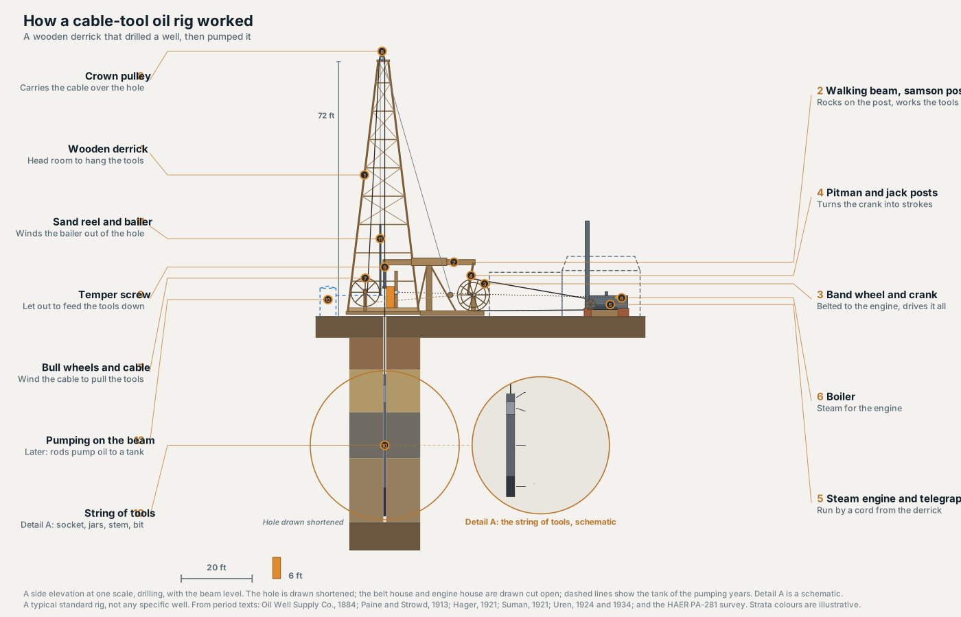
We built one you can take apart: a wooden standard rig, laid out the way the Oil Well Supply Company's 1884 catalogue lays it out, timber by timber, with its stroke, tools and controls from textbooks of 1913 to 1934 and its pumping well from a survey by the Historic American Engineering Record. It drills, and at the press of a button it pumps on the same beam. It is a type of rig, not a picture of any real well, built from public records the way we built our pump jack, our FPSO and our LNG plant. The tour runs 47 seconds with no sound, and every label is on screen.
Take it apart yourself.
The model runs in your browser. Drag to turn it, take it apart with the slider, and press Cut it open to see the tools at the bottom of the hole. Show it pumping hangs sucker rods where the tools hung, and Find the people marks the crew. Each of the twelve parts has its own card. It works on a phone.
It sits beside our offshore structures, the pump jack, the LNG plant and the data hall. See all the exhibits.
The carpenter's rig
A rig like this was built on the spot, out of lumber. The 1884 catalogue, from a supply house in Bradford and Oil City, Pennsylvania, starts with the ground: "a space about 90 feet long by 25 feet wide should be cleared and levelled." Then it gives every timber. The derrick stands directly over the well, 20 feet square at the base and 72 feet high, with eight rows of girths tying its legs and braces between them. Low on the side nearest the beam, the braces are left out so the walking beam can move. Behind the derrick a samson post 13 feet high carries a walking beam 26 feet long. The whole rig takes "about fifteen thousand feet, board measure," of lumber, not counting the wheels and the sand reel, "as it is better to buy them complete."
Was this one supply house's design, or the common one? Paine and Strowd, in a 1913 text published in San Francisco, describe a 20 by 74 derrick and say "this size has been used probably more than any other," with heights in recent practice going toward 84 feet for cable tools and to 106, 114 and even 124 feet for the rotary. In 1921 John Suman found "almost everyone" in the deep cable tool country of North Texas on an 84 foot derrick with a 22 foot base. His bill of materials for that rig lists the same timbers, a beam, a samson post, a jack post and a pitman among them, in 28,656 board feet of pine and oak against the catalogue's fifteen thousand. For almost forty years the rig grew without changing its parts.
Spudding, then hitching on
The beam could not drill the first hole. The tools had to hang below the derrick floor before the beam could work them, and a string of tools is tall. So the beam waited. Uren gives the reason and the remedy: with a string 40 feet long or more, there was not enough head room to drill with the walking beam until the hole was at least 60 feet deep, so the first 60 feet, and frequently several hundred, were drilled by a process called spudding, which did not use the beam at all. The 1884 catalogue says the same of its longer tools: "The first sixty feet are 'spudded.'"
Paine and Strowd describe the change of gear that followed. When the stem was deep enough to be covered by the walls of the hole, the wrist pin went into the third hole of the crank "to permit of a longer stroke and a harder blow," and at 130 to 150 feet "it is customary to substitute the walking-beam for the jerk-line. This is called 'hitching on'." From then on the pitman and the beam did the work. Our drawing works the beam on a hole only 58 feet deep, shallower than any hole a driller hitched on to, because a true depth would put the tools off the bottom of the screen.
From the engine to the bit
Follow one stroke. The engine had a single cylinder, "a simple slide valve, and link reversing gear of the locomotive type," and in the eastern United States a 9 by 12 inch engine was the common size for cable tools (Paine and Strowd). The 1884 catalogue sets it at least 33 feet from the band wheel, a wooden wheel 9 feet across that "communicates power to all the movable parts of the apparatus." On the band wheel's shaft is a crank, and the pitman runs from its wrist pin up to the back end of the beam. Each turn of the crank pulls that end down and lets it rise. The front end, 25 feet from the pitman with the samson post midway, lifts the tools and lets them fall.
How far they fall is set at the crank. Uren's first edition gives the crank five holes for the wrist pin, "each successive hole in the crank adding 6 in. to the sweep of the beam," and puts the sweep at 2 to 5 feet. Four steps of 6 inches make 2 feet, not 3, so the two figures in that sentence do not agree. His second edition, in 1934, gives 2 1/4 to 4 1/4 feet, which the steps do make, and that is the range we drew: the drawing drills on the middle hole, a sweep of 3 1/4 feet, at 30 strokes a minute.
The tools fall further than the beam moves, because the cable stretches. Uren works the numbers for a sweep of "say, 3 ft.": a drop of perhaps 5 or 6 feet with the stretch, 3,600 pounds of tools, and "18,000 ft.-lb. of work exerted on the formation at each stroke." Hager adds the condition that made it drilling and not hammering: "The tools when in the hole must swing free of bottom at their lowest point." The beam stops; the cable keeps going. "The tools will lash out 4 or 5 ft. and strike bottom with terrific force."
What the driller worked by hand
The driller stood on the derrick floor, more than 33 feet from the engine, and ran it from there. In Paine and Strowd's words, "The engine is operated from the derrick by pulling back and forth the 'telegraph cord' ... which runs from a wheel attached to the headache-post to the throttle-wheel." The reverse lever was worked "in a like manner" by a 3/8 or 1/2 inch pipe. Speed and direction both came to his hand. The headache post itself, under the front of the beam, explains its name in the 1884 catalogue: if the pitman or the saddle broke, the front end of the beam "would drop upon it, and thus be prevented from falling on the head" of the driller.
The temper screw fed the tools down. It was a 2 inch screw 5 or 6 feet long with coarse square threads, hung in a slot on the beam, and a counterweight rigged behind the samson post helped pull it back after it had been let out (Paine and Strowd). The drilling clamps that held the cable were fixed to its lower end, and Suman gives it a let out of 60 to 70 inches. As the bit cut, the driller let out screw. Then the tools came out. The bull rope, an endless rope from a tug pulley on the side of the band wheel, turned the bull wheels and wound the cable in (Uren). The sand reel sent the bailer down to clean out the cuttings: the reel sat on a movable cradle, so its friction pulley could be brought against the face of the band wheel to wind the bailer up, and the bailer went back down by its own weight under a post brake (Uren). Over it all, at the top of the derrick, hung the crown pulley, 18 inches across.
Two men ran all of it around the clock. Uren describes 2 or 3 crews working 12 or 8 hours each, every crew "the driller, who is in responsible charge of the work, and his helper or tool dresser," and the work "divided into alternate periods of drilling and bailing." Hager has two tours of 12 hours, "pronounced like tower." Uren's 1934 edition puts the boiler near the well, under the immediate control of the driller and the tool dresser, and gives its care to the tool dresser in his spare moments. So picture the night tour: the driller at the temper screw with one hand on the cable, the tool dresser off the floor for a few minutes to look to the boiler, the engine more than 33 feet off in its house, and the beam rising and falling thirty times a minute over a hole that neither of them can see into.
Nobody saw the bit
Everything the driller knew about the bottom of the hole came up the cable or out of the bailer. Hager is exact about the cable: "Experienced drillers tell from the feel of the tools whether or not the bit is striking a solid blow. The “pick up” of the cable is the measure of the blow." The pick up was the feel of the tension on the line, and it told the driller whether the tools were "striking bottom or swinging free in the hole." The string of tools was a few feet off bottom at the top of the stroke and on the rock at the end of the lash, and the temper screw was how he kept it there.
Uren lists what the hand and the bailer told him: "The cable tool driller is able to identify the kind of rock in which the drill is operating by the rate of progress, by the jar on the drilling cable and by the wear on the drilling tools." The bailer brought up mostly mud. A little of it, washed in a bucket, left the coarser grains to look at. Depth came from a mark: the driller kept "a “target” or reference mark" on the line at the approximate depth to bottom, and measured past it with a steel tape or a 5 foot stick, "which is a part of the equipment of every cable drilling rig." Uren adds, drily, that "many drillers do not attempt measurements within the 5-ft. length of the stick."
He also prints a table of what each rock felt like, after R. E. Collom's 1922 Bureau of Mines bulletin. Six of its rows are from southern Oklahoma and one from the Ranger field in Texas, word for word:
| Rock | On the cable and beam | In the bailer | On the bit |
|---|---|---|---|
| Shale, southern Oklahoma | Tools run smoothly and drill easily and fast in dry hole. | Bailer material mostly mud; fragments in mud and occasionally on bit. | Does not wear bit. |
| Gumbo, southern Oklahoma | Drills roughly; tools jerk walking beam and do not drop freely. | Bailer material mud; tools come out loaded with gumbo. | Does not wear bit. |
| Soft sand, southern Oklahoma | Drills fast and easily; tools plunge. | Sand in bailer; none on bit. | No wear on bit, but markings vertical. |
| Sandstone, southern Oklahoma | Drills smoothly with occasional “kick back.” | Grains of sand and chunks of sandstone in bailer. | Wears bit out of gage. |
| Limestone, southern Oklahoma | Hard and slow drilling; big “kick back.” | Chips and irregular pieces, rock mostly pulverized. | Wears bit, but does not cause to lose gage like sandstone. |
| Gypsum, southern Oklahoma | Drills smoothly and more easily than crystalline limestone. | Mostly pulverized; occasional flakes. | Does not wear bit excessively. |
| White limestone, Ranger field, Texas | Drills hard but free, with tight line. | White and pulverized. | Cuts bit badly: 3 bits per tour. |
A tour, in the last row, is a crew's shift. Three bits in one shift. The rotary rig lost most of this, and Uren says so. At the mud ditch of a rotary well, "Clays and shales will usually be so finely pulverized by the drill that the color imparted to the circulating fluid by them is the only means of identifying one stratum from another." And: "Because of the rapid progress made in soft formations, and the difficulty of recognizing slight changes in the nature of strata penetrated, the rotary method does not yield so reliable and complete a log as the churn drilling method." That is the reason behind his "preferable" for wildcats.
None of it stayed in the driller's head. "Drillers prepare tour reports for their foreman," Uren writes, and he prints a blank Driller's Tour Report. The same passage carries the chain upward: the foreman "combines these with a report to the superintendent of development," and so on up through the general manager, because "every individual should be responsible to someone directly over him in authority, for a periodical report on work accomplished and the results thereof."
We should not make too much of this. The table is words for a feel, set down by an engineer for students who had never stood at a temper screw, and a tour report is a form, not a measurement. But the arrangement is one we find in every exhibit we build: a signal only one person can read, a judgment made on it at the well, and a report that lets someone further up check that judgment later and answer for what was done. That is how a well was drilled in 1924, and it is the question we ask of any model put to work on a well today. Who reads the signal, who decides, and what is written down? That is what we mean by AI decision governance, and we cover the modern version in how oil and gas companies use AI, and the governance it needs.
The same beam, pumping
The rig stayed. Hager says that on wells deeper than 1,500 feet it was customary to build heavy derricks, which as a rule were left in place after a paying well was obtained. The beam that had dropped the tools lifted sucker rods instead, and the engine ran slower: "The speed of the pumps ranges from 10 strokes per minute for very heavy oil to as high as 20 strokes per minute for lighter oil. With the walking beam the second hole is used, which gives a 16-in. stroke," or 18 inches on some rigs.
The Historic American Engineering Record surveyed one such rig in Butler County, Pennsylvania, in 1992. The David Renfrew rig was drilled in or after 1881, when oil was first struck in its field, and by a neighbour's account it was still pumping as late as 1950, though he was not sure whether it was lifting oil or water. By then most of it had been replaced. The derrick was tubular metal, the walking beam and samson post were doubled metal pipe, and the last engine to drive it was a six cylinder automobile engine from about 1920. The band wheel was still wood, 9 feet 4 inches across against the catalogue's 9 feet, and so was the hand hewn pitman, "of the type used on the earliest rigs." Its sucker rods worked inside iron tubing about 2 inches across, in casing about 5 inches across, with valves at the bottom, a standing valve and a working valve. A pipe about 6 feet off the ground carried the oil to a steel receiving tank about 4 feet 6 inches in diameter and 8 feet tall.
Our rig pumps at 12 strokes a minute, inside Hager's range, on the innermost of its five crank holes, a stroke of 27 inches. A pump jack does this same job today on a steel frame of its own, with a motor where the steam engine was, and our pump jack article follows one stroke from that motor to the bottom of the well. Open the pump jack exhibit beside this one and the family resemblance is plain.
1884 to about 1950
How old is this rig? Our sources date it loosely, and we have kept to what they say. The 1884 catalogue is the earliest full description we used, and it already lays the rig out as a standard set of timbers. Paine and Strowd in 1913 call the 20 by 74 derrick the size used "probably more than any other." Suman in 1921 has nearly everyone in North Texas on a bigger version of it. The Renfrew rig, rebuilt in metal around its wooden band wheel and pitman, was still pumping something in 1950. So the type was fully described by 1884, the common rig through the 1910s, still growing in the 1920s, and in at least one case still working, in patched form, after the Second World War.
The oil business is older than these books, and we have left that earlier story out, since none of our sources covers it. We make no claim about when the rotary rig replaced cable tools either, because our sources show the two working side by side in the 1910s and 1920s, and Uren, in 1924, gives the rotary the deep wells into known targets and the soft ground. One sentence moved, though. Where Uren's 1924 edition says the cable method "is preferable" for wildcat wells, his 1934 edition says it "is sometimes preferred." That is one author revising one sentence over ten years. It tells you how his view moved, not when the industry's did.
Where our rig departs from the books
Some of it is ours. We list it here so that nobody takes it for a source:
- The hole is drawn short. A real hole was spudded to at least 60 feet and hitched on to the beam at 130 to 150, so the beam never worked a hole as shallow as the one on screen, and everything below the tools in a real well of this kind is depth we left out.
- The sources disagree on the tools. The 1884 catalogue's string is sixty feet long and about 2,400 pounds. Uren's, forty years later, is about 40 feet and 3,600 pounds for a 10 inch hole. We drew Uren's. Only its total length and the bit's are sourced; the split into rope socket, jars, stem and bit is the drawing's.
- The crank's range is from the second edition. Uren's 1924 edition prints a sweep of 2 to 5 feet, which its own 6 inch steps cannot make, so we took 2 1/4 to 4 1/4 feet from his 1934 edition. Archive.org catalogues that edition as 1924; the first edition is a separate scan, and both are listed below.
- The pumping stroke is longer than Hager's. His 16 inch stroke belongs to a crank drilled on a different pattern; ours pumps on the innermost of Uren's five holes, at 27 inches.
- The well sits 5 inches off centre. That follows the 1884 catalogue's crown pulley. Paine and Strowd, in 1913, start the well 8 or 9 feet from the front side of the floor, towards the engine house.
- The fireman is ours. Uren and Hager both describe a crew of two, and Uren's 1934 edition gives the boiler to the tool dresser. We drew a third figure at the boiler, which neither of them has.
- The houses are ordinary, not measured. The engine house and boiler setting are the right kind for a rig like this, not copies of one. The catalogue also says that in winter "the whole rig is enclosed"; ours is drawn open.
- The ground is a tile. The strata colours are bands for legibility, not the geology of any place.
Read the books, and send us yours
Every source below is online. The 1884 catalogue walks you through building the rig timber by timber, Hager writes for men who ran one, and Uren's chapter on churn drilling is the best single account we found. If someone in your family drilled with cable tools and you still have a tour report, a photograph of a rig, or the story of how they read a hole by the feel of the line, we would like to see it, because that is the part of this story the textbooks left out. Send it to us. And if you know these rigs and something here is drawn wrong, tell us what, and we will fix it.
Sources
- Oil Well Supply Co., Illustrated Catalogue of Oil and Artesian Well Supplies, Bradford and Oil City, Pennsylvania (1884), The Carpenter's Rig
- Paul M. Paine and B. K. Strowd, Oil Production Methods (San Francisco, 1913)
- Dorsey Hager, Oil-Field Practice (New York, 1921)
- John R. Suman, Petroleum Production Methods (Houston, 1921)
- Lester C. Uren, Petroleum Production Engineering: Oil Field Development, first edition (New York, 1924). Its Table XII is after R. E. Collom, US Bureau of Mines Bulletin 201 (1922)
- Lester C. Uren, Petroleum Production Engineering: Oil Field Development, second edition (New York, 1934). Archive.org catalogues this scan as 1924
- Historic American Engineering Record, David Renfrew Oil Rig, Renfrew, Butler County, Pennsylvania, HAER PA-281 (Library of Congress)